Resolvers vs. encoders for motion control
Article provided by sister company RENCO Encoders, Inc.
The phrase “more precise control” would generally drive the solution towards an encoder over a resolver. The application of dry food packaging however might tend to drive it back towards a resolver. Here are some characteristics you can consider to help make the decision.

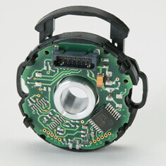
RENCO R35i

Environmental Protection – Encoders and resolvers can be packaged in basically the same ways, so there is no advantage to one or the other as far as environmental protection.
Operating Environment – The resolver is sturdy and possibly more suitable for a severe environment application where extreme continuous temperatures or very high vibration might be encountered. However, an encoder can be very robust as well, so the only real advantage here would be the ability of the resolver to withstand higher continuous temperatures. If your application requires the feedback device to run at over 125 degrees Celsius, you should probably go with the resolver.
Complexity – Most motion control systems can work with resolvers or encoders, so there is no real difference in wires and interconnects. However, resolvers are analog devices and they require a converter to format the measurement for processing by a digital computer. This conversion is done by a resolver to digital converter, (RDC) or by a DSP and suitable input filtering circuitry. The application must carefully consider a number of parameters and select fixed components in order to successfully utilize a resolver in any given application. The minimum resolver application must consider reference frequency, bandwidth, maximum tracking rate, number of bits in the conversion result, input filtering, AC coupling of the reference, phase compensation of the signal and reference, and offset adjustment. All of these issues will affect the measurement process and affect the overall accuracy of the control loop. As an example, something like the Analog Devices AD2S80A can be used. Converters of this type are tracking converters, which are implemented using a type two servo. A type two servo is a closed loop control system, which is characterized as having zero error for constant velocity or stationary inputs. Conversely, this type of system will demonstrate errors in all other situations, and the magnitude of these errors must be controlled through optimized “tuning” of the converter. The fact that the converter itself has dynamics becomes an important part of the system design. Being type two, the converter can introduce up to 180 degrees of phase lag into the system. For a 12 bit converter using a 400 Hz reference (pages 11 and 12), the RDC bandwidth (-3db point) will be less than 100Hz. Using the same reference, a 14 bit converter will have a bandwidth of 66 Hz, and a 16 bit converter will have a bandwidth of 53 Hz. A 100 Hz -3db bandwidth means that there will be approximately 3db of peaking and 45° of phase shift at 40 Hz. As many servos attempt to close position loops near these frequencies, an added 45° phase shift would be undesirable. It should also be noted that, although the RDC tracking rate may not be exceeded, a system with difficult load dynamics could well prove unstable when the RDC dynamics are introduced. The situation only worsens when 14 bit or 16 bit converters are utilized. Another feature of the RDC is that the maximum slew, or tracking rate, is limited by the resolver reference, or carrier, frequency. For example, the Analog Devices AD2S80A RDC, using a 400 Hz reference, will have a tracking limit of 1500 rpm. This value can be increased to 18,750 rpm using a 5kHz reference. In contrast, encoders can be much simpler. When an encoder is used in a control system, there are only two issues to consider, desired resolution and the maximum rpm the encoder will need to work at. There are also no encoder dynamics to deal with as the measurement process is fundamentally digital. An encoder provides data with guaranteed signal separation and symmetry at up to the rated speed, and that is all there is. Many encoders are now available with resolutions up to 25 bits, and some are capable of allowing the motors to run at 10,000 rpm with close to this resolution. As a result, an encoder based application will generally have a wider dynamic range capability.
Data Format – Resolvers are “absolute” measurement systems. They provide a unique Sin/Cos voltage at every point in a 360 degree rotation. An encoder can be absolute or incremental, and the output will be digital. Absolute encoders usually have a serial databus, which the drive must be able to communicate with in order to read out the position measurement. This requires the designer to verify the encoder and the drive are compatible. Incremental encoders are ubiquitous and every drive made can interface to them.
Accuracy – An encoder will be more accurate than a resolver and its associated conversion process.
Flexibility – If at some point in the future more performance or positioning accuracy becomes necessary, it will be much easier to upgrade an encoder based system. An encoder application will require only the feedback element to be replaced, and a software change to the drive so that the new line count is accounted for. A resolver change will require reconsideration of the associated converter, supply voltage and frequency, filtering, etc., and this may not be possible to change unless the drive has been developed with this in mind.
SUMMARY
Resolvers provide absolute position information and are capable of operating in relatively high temperature and shock environments because they are similar in construction to the motor itself. However, they are inflexible in their application, and must be specifically “tuned” to meet the drive system requirements. Encoders on the other hand, can be absolute or incremental, simplify the design task, are more accurate, allow for a wider dynamic range and are more flexible should changes be necessary in the future.

