Frequently Asked Questions (FAQ)

Frequently asked questions at our HEIDENHAIN Service department
Please select your topic and question. If you can’t find what you’re looking for, please contact our Helpline.
General
If you can’t remember your password, then you can request it by clicking “Forgot your password?” on the login screen.
You can find information about our products, including mounting instructions, in “HIF” (for customers with access information) or at our Infobase. Please send any further questions to hesis-web@heidenhain.de.
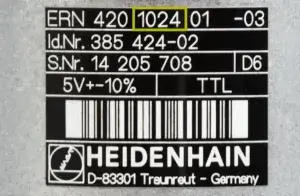
ID label from HEIDENHAIN
HEIDENHAIN components normally have a black ID label (often on the back). Here you’ll find the ID number and serial number, as well as the model designation. On connecting cables, the ID number is on the jacket, near the connector.
With your serial number on hand, please contact the HEIDENHAIN Service department: techsupportHC@heidenhain.com.
Repairs, replacement parts, and replacement devices
A courier service is possible within Germany and, to a limited extent, abroad. Contact the HEIDENHAIN Service department: serviceadminHC@heidenhain.com
You can pick up your device at HEIDENHAIN yourself. Please inform us two hours in advance. Pickup is possible only with the order number.
It is generally possible to wait for a repair at the HEIDENHAIN US headquarters in Schaumburg and regional agencies. Please first get in touch with the Encoders & DRO Support team:
For questions about repairs being made to your control, please contact the HEIDENHAIN Service department:
serviceadminHC@heidenhain.com
Please contact the customer service to setup a service return authorization (SRA): techsupportHC@heidenhain.com
After receiving the SRA, please ship the unit to our US headquarters in Schaumburg, IL:
HEIDENHAIN CORPORATION
333 East State Parkway
Schaumburg, IL 60173
Contact the HEIDENHAIN Service department: techsupportHC@heidenhain.com
Contact our HEIDENHAIN Service department: techsupportHC@heidenhain.com
You can request an inspection report from the relevant customer service representative: serviceadminHC@heidenhain.com
Please contact the HEIDENHAIN Service department: techsupportHC@heidenhain.com
For the HEIDENHAIN exchange service, please always send your defective devices to the address at which you requested the exchange. You can find your HEIDENHAIN regional agency here.
North American campus shipping address for defective devices as part of the exchange service:
HEIDENHAIN CORPORATION
333 East State Parkway
Schaumburg, IL 60173
In this case, please note the replacement order number on your delivery receipt.
HEIDENHAIN uses the following shipping carriers:
- UPS
- FedEx
- DHL
- TNT
Product warranties
Our customers have a contractual, 12-month guarantee on serial devices. In addition, HEIDENHAIN provides a 24-month performance warranty. The total performance warranty period for new serial devices is therefore 36 months.
Devices for servicing purposes
A 12-month performance warranty applies to replacement parts.
Replacement devices
A 12-month performance warranty applies to devices from our Service Exchange inventory.
Repairs
After the repair, you receive a 12-month performance warranty on both the repaired part and the entire device.
In addition to an extended warranty (24 months), HEIDENHAIN also offers service agreements that increase the cost-efficiency of your investment and make repair costs plannable. We offer the following:
- Extension of the warranty period
- Stock-keeping
Please get in touch with your contact person in the Sales department.
Contact the HEIDENHAIN Service department:
serviceadminHC@heidenhain.com
CNC controls
AVD: Active Vibration Damping
CTC: Cross Talk Compensation
ACC: Active Chatter Control
PAC: Position Adaptive Control
MAC: Motion Adaptive Control
LAC: Load Adaptive Control
For detailed descriptions, visit these links:
https://www.klartext-portal.com/en/tips/functions/dynamic-precision/
https://www.klartext-portal.com/en/tips/functions/dynamic-efficiency/
For the purpose of error diagnosis, all error messages and keystrokes are documented in a log.
A log can be created on the control via the “LOGBOOK” code number or via the ERR button → LOG FILES soft key → LOG on more current controls.
There is also the possibility of creating a log from an external PC via TNCremo: go the “Extras” menu and select “Receive log”.
The Infobase provides you with full information about our products.
Search the User’s Manual for the respective ID or “Clone”.
You can find the information in the machine manual from the machine manufacturer. Press the “ERR” and then the “HELP” key. To find more information about PLC messages in the machine manual and about NC messages, visit the following link: https://content.heidenhain.de/doku/tnc_guide/html/en/index/1242135142456/1242135142456.html
Your e-mail should ideally contain the following information:
- Ticket number (if known)
- Your corporate address
- Person of contact (if a phone call has taken place)
- Precise description of the error
- Servicing file (created directly after the error occurred)
- The control model
- The machine manufacturer
If needed, feel free to schedule a call with a TNC technician.
There are several possibilities depending on what is needed:
– TNCremo PLUS –
This allows you to display a live image of your control.
For more information, please refer to the following link:
https://www.heidenhain.us/products/digital-shop-floor/connected-machining/
– TeleService –
This lets you display a live image of your control and operate it.
– StateMonitor –
This gives you fundamental information about machine availability, whether a program is running, or whether an error is shown. For more information, please refer to the following link:
https://www.klartext-portal.com/en/software/machine-data-collection/
– SRI State Reporting Interface –
With its State Reporting Interface (SRI) software option, HEIDENHAIN offers an interface for easily making machine operating statuses available to a higher-level MES or ERP system.
Newer controls (TNC 4xx or later) feature a GoldCap capacitor, which ensures that the data are buffered while the battery is being changed. However, the battery should not be removed for an extended period of time. Older controls do not have a capacitor, and their data are not saved when the control is switched off.
In HSCI systems, the states of various inputs and outputs can be checked via the HSCI bus diagnostics. In non-HSCI systems, the “TABLE” soft key in the PLC (password required) allows you to check the inputs and outputs.
- The User’s Manuals for NC programmers/machine operators can be found under Documentation in the download area.
- The Technical Manuals and Service Manuals for current controls (iTNC 530 and NCK controls) are in the HEIDENHAIN Filebase for authorized customers.
- The Technical Manuals and various service documents of older controls are available to everyone for download under Documentation.
Please get in touch with your machine manufacturer. Tool changer systems are OEM-specific hardware.
Different methods are possible depending on the type of control. These possibilities are described in detail in the respective User’s Manual.
Tip: search for “data backup” in the PDF document.
Please check the following:
- Can the machine be reached by a ping?
- Is option 18 enabled?
- Is external access activated?
- Are all necessary ports enabled in the firewall?
The easiest way to establish a connection to the TNC from a directly connected PC is with TNCremo/TNCserver.
If the TNC control already has a network card (iTNC 530 or higher), then at least one IP address must be provided. Please refer to the description in the User’s Manual, because the procedure varies slightly based on the NC software.
All of the TNC controls also feature an RS-232 interface (Recommended Standard 232). But due to its very limited capabilities and speed, this interface should be used only on older models.
In order to integrate an indexing head into an already existing system, you need to contact the machine manufacturer. The machine manufacturer can provide you with detailed information about feasibility and may perform the installation.
If the LAN cable is connected to a switch/hub in the network, and if the IP address is set accordingly on the TNC, then the transmission of data to and from the TNC can be started through the use of the machine’s IP address with TNCremo, for example.
The MillPlus was a control designed exclusively for DMG. For this reason, DMG is responsible for answering questions about the MillPlus.
Depending on the type of network share and version, it can be made visible as a drive on the TNC. Because this process varies slightly based on the NC software, please refer to the User’s Manual.
- Press the ERR key
- The LOG FILES soft key should now appear
- Press the LOG FILES soft key
- Press the SAVE SERVICE FILES soft key
Please contact the HEIDENHAIN NC Support & PLC Programming Support:
TNCService@heidenhain.com
In software version 606420-04 SP12, we introduced machine parameter MP2207.x (overwrite “Type of temperature sensor” from motor table). This machine parameter can be modified as follows:
* = Entry in the motor table is active
0 = KTY84-130
1 = PT1000
In NC software 606420-04 SP5 or later, the motor table contains the entry “TEMP_SENS”. You can change this entry with a PLC authorization.
For older controls, we offer the PT1000-KTY converter (ID: 1219990-02).
This can be done with the help of software for collecting operating data. HEIDENHAIN offers StateMonitor as a solution for the TNC.
The behavior of the “actual position capture” key was intentionally changed for the introduction of NC software 340590-10. The value is now always taken from the value of the programmed tool axis as shown in the position display. To receive the correct value, perform the following steps:
1. Enter L=0 and DL=0 for the tool, and move the tool to the touch-off surface.
2. Press the “actual position capture” key.
The displayed value is always transferred to the table without undergoing any calculations. This process also takes the programmed tool axis into account rather than merely “Z”.
We recommend contacting your machine manufacturer or a qualified retrofitter.
We can happily recommend experienced companies. Please contact TNCService@heidenhain.com
In this case, an analysis of the service file should be performed by the HEIDENHAIN Service team. Please contact the NC Support helpline by phone: +49 8669 31-3101 or e-mail:
Software
You can obtain the current version in our download area.
The machine manufacturer enables those software versions that are suitable and tested for the given machine type. Please get in touch with the machine manufacturer about this.
Please contact the HEIDENHAIN TNC Support group TNCservice@heidenhain.com
The NC software version is shown when the MOD key is pressed in Manual operating mode.
Please contact your machine manufacturer.
For a list of the ports, please refer to the “Requirements” section in the StateMonitor user documentation.
- Start the “Create HeidenhainDNC connections” program, located in %PROGRAMFILES(x86)%\HEIDENHAIN\SDK\Connections.
- After pressing the “DNC Logging” button, the HEIDENHAIN DNC Logging Features dialog box appears.
- Only the “Main objects / Basic” option is set as a default. After selecting all options, you can re-close the dialog box by pressing the “OK” button.
- Restart your application in order for the changes to take effect.
When the MOD key is pressed in Programming/Editing mode, a list of the currently enabled machine options can be shown upon entry of the “SIK” code number.
Programming station
- Enter “System information” into the Windows search field.
- Open the “System Information” app and scroll all the way down to the bottom.
- Check whether the following entry is shown: “A hypervisor has been detected. Features required for Hyper-V are not displayed.”
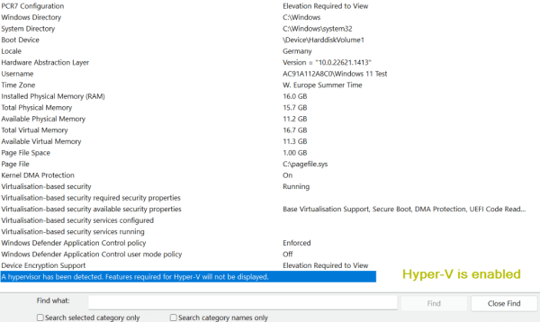
Example: Hyper-V is enabled
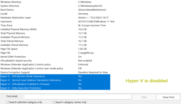
Example: Hyper-V is disabled
Note the system requirements along with the following information:
- HEIDENHAIN has no influence over which applications are installed on a PC or which Windows features are needed. Please check whether the use of the programming station software, including VirtualBox, is possible on the intended PC. Also check which feature uses Hyper-V and whether you can deactivate this feature along with Hyper-V.
- As an alternative to VBox, you can install VMware Workstation. If you do this, then the option of using VMware Workstation is offered during the customized installation of the programming station software. Please note: It is not possible to install the programming station software in the VMware Workstation Player!
- Test the installation of the programming station software with Hyper-V enabled to see whether it is sufficient for your needs. Although this combination is possible, a warning appears both when the programming station software is installed and when it is started. This combination may not be suitable for productive use of the programming station.
The name of the programming station to be installed is automatically assigned during installation in “Default” mode.
If you wish to install more than one programming station of the same control on a computer, select “Custom” during installation. You can now assign any name to the programming station and thus install multiple programming stations of the same control on your PC.
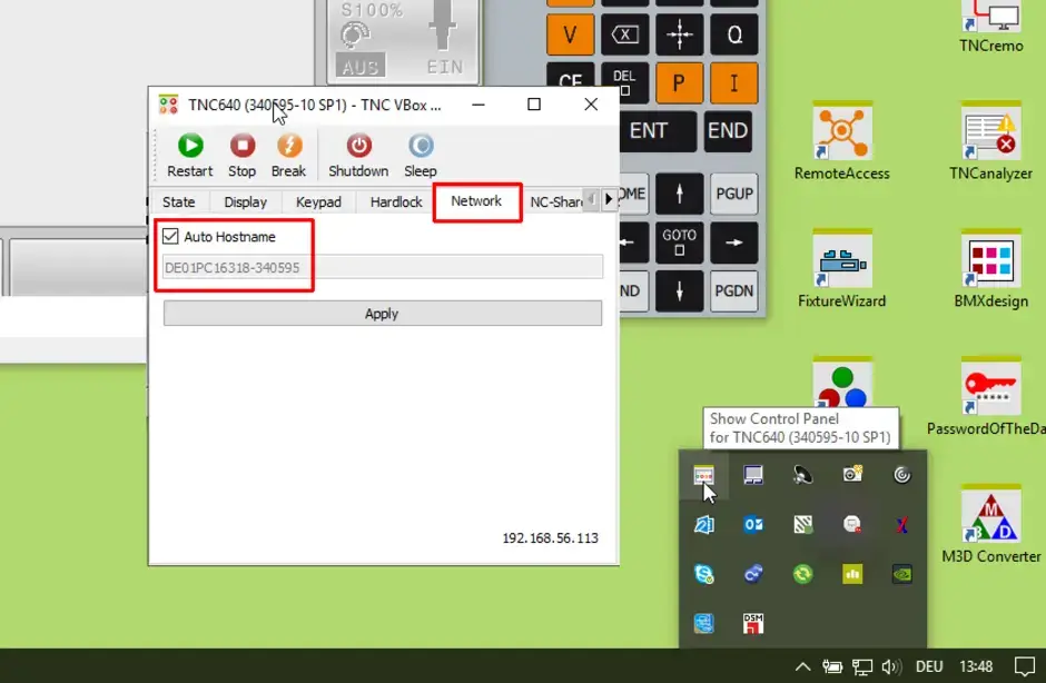
Establishing a connection with TNCremo
It is possible to transfer data with the TNCremo program provided by HEIDENHAIN, just as on the real machine.
- Download the most current TNCremo version.
- Unpack the ZIP file (e.g., WinZip or 7-Zip).
- Run Setup.exe, and follow the instructions of the installation wizard.
- After successful installation, a new TNCremo desktop icon is created.
- Start the TNCremo software with the newly created desktop icon.
- Establish a new connection via the Connection tab.
- New configuration
- Enter a recognizable name for this connection (e.g., “TNC640 Prog”).
- Select the installed programming station to which the connection should be established.
- When selecting “Local programming station VirtualBox,” the IP address must be modified in the Settings tab.
- Determine the address via the Control Panel.
- Connection with Connection tab: establish the connection.
- The screen in TNCremo splits, and the TNC:\ programming station partition is displayed.
This cannot be answered across the board and sometimes depends on other factors such as a graphics driver. To find out the operating systems for which the individual versions are released, see the information in the download area.
It is sometimes possible to adapt a current and therefore runnable programming station to the cycle structure of an older version, thus allowing programming errors to be reduced.
As a last option, a Windows XP computer, for example, can be used in a virtual environment in order to install the old programming station.
We recommend the same procedure as on the real machine:
- Connection to a network drive on which all NC programs are saved, and transference via Program Management on the programming station.
- Use of TNCremo on this or another PC in the network.
Some machine manufacturers offer an adapted programming station (digital twin) for their machines. Alternatively, the HEIDENHAIN Service department can offer to perform an adaptation. However, the full transference of all functions cannot be guaranteed.
Contact person – Service
NC Support & PLC Programming Support
+1 847 490 0351
TNCService@heidenhain.com
The software of the test version and full version is identical. It is enabled via a hardware dongle that is ordinarily built into the programming station keyboard. Whether this kind of dongle or an external dongle is connected depends on the given driver. The driver can be downloaded from our website free of charge but is dependent on the model. If you are unsure, then simply install both drivers.
If the dongle is displayed correctly in the Windows device manager and is still not recognized by the software, then this may be due to the following:
- Incorrect software version; dongle license does not match
- VirtualBox does not use the dongle properly → Check installation
- Multiple programming station are running (the first one becomes the full version)
- Download the most recent version of the VirtualBox programming station of the TNC 640 from the download area in order to ensure that the installation file is up to date.
- Open the downloaded .zip file with a right-click.
- Navigate to the “Properties” context menu → “General” tab → Security (The file originates from a different computer. Access might be denied due to safety reasons.) → Click the “Unblock” checkbox.
- Unpack the .zip file, and then install the programming station. It is important that you have administrator permissions on the installation PC.
The programming station installation process checks whether hardware virtualization is present and active.
Smooth operation of the programming station in conjunction with the VirtualBox virtualization software requires the availability of hardware virtualization. The processor thus needs to have the VT-x or AMD-V instruction set extension. The availability of hardware virtualization depends not only on the CPU but also on the settings in the BIOS and the Windows operating system of your PC. Be sure to consider all relevant information provided by the manufacturer!
In the Task Manager, check whether >Enabled< appears next to “Virtualization” within the “Performance” tab.
Third-party virtualization applications, such as ORACLE VirtualBox or VMware Workstation, rely on the Intel VT-x or AMD-V instruction set extensions, which are available on most current processors. However, they are no longer fully available to the virtualization application if Microsoft already uses these instruction set extensions for its own functions, such as Hyper-V, WSL2 and virtualization-based security.
In order to use third-party virtualization software with hardware virtualization, you must deactivate the abovementioned functions on your PC.
Alternatively, when Hyper-V is enabled, the third-party virtualization applications can use a software interface as a replacement for the abovementioned instruction set extensions. This can result in performance losses and limited functionality that has an effect, for example, when the programming station is used in conjunction with VirtualBox. Although this combination is possible, a warning appears both when the programming station software is installed and when it is started. This combination may not be suitable for productive use of the programming station software.
HEIDENHAIN has no influence over which applications are installed on a PC or which Windows features are needed. Please check whether the use of the programming station software, including VirtualBox, is possible on the intended PC.
It is possible to use VMware Workstation as an alternative if enabling Hyper-V is unavoidable on your PC. When VMware Workstation 16 or later is used in conjunction with Windows 10 20H2, it is possible to enable Hyper-V and use VMware Workstation as a virtualizer for the programming station software with only minor performance losses. Not all versions of the programming station software are prepared for installation with VMware Workstation. VMware Workstation is not part of the installation package of the programming station software and must be installed by the user. Please note: It is not possible to install the programming station software in the VMware Workstation Player.
NC programming
If the file was created in the correct format, then it can be copied to the TNC with the extension “.a” via TNCremo or a USB drive. Once on the TNC, it can be copied from the program manager to the active Tool.t via the “Copy” function. It is also possible to “merge” the file directly into the Tool.t via TNCcmd. Both procedures are described in the User’s Manual and may vary slightly depending on the TNC.
A standard editor can be used. It is important that the columns not be moved. Missing characters must be replaced by spaces (note: no tab stop).
With the BLANK IN WORKING SPACE soft key, the preset set in Manual operating mode can be used in the simulation.
- Switch to Test Run mode.
- Select a machining program.
- Press the BLANK IN WORKING SPACE soft key.
- Press the soft key with the machine icon.
Note: The path description to this soft key may differ on older control types. Refer to the User’s Manual of your software version as needed.
This is because Cycles 220 and 221 are DEF-active and do not need to be started separately. If, however, an M99 function or CYCL CALL is programmed, then the machining cycle is run again at the same point at which Cycle 22x ends.
This message is output by the TNC when no suitable solution can be calculated with the entered values. This could be caused by incorrect or missing sequences (SEQ), a limited traversing range, an incorrect kinematic description, or a missing M138 function on a machine with three rotary axes.
No, in this case, even ISO programming is specific to the control. The only exceptions are programs that contain only G0 and G1, but the header must also be changed.
The postprocessor must always be purchased from the CAM system manufacturer. Whether 2D, 3D (inclined machining), or 3D simultaneous machining is required depends on the machine, the NC software, and, of course, on the range of parts to be machined.
Encoders
Our infobase will tell you everything about our products. You can search for your encoder based on your ID number or product name.
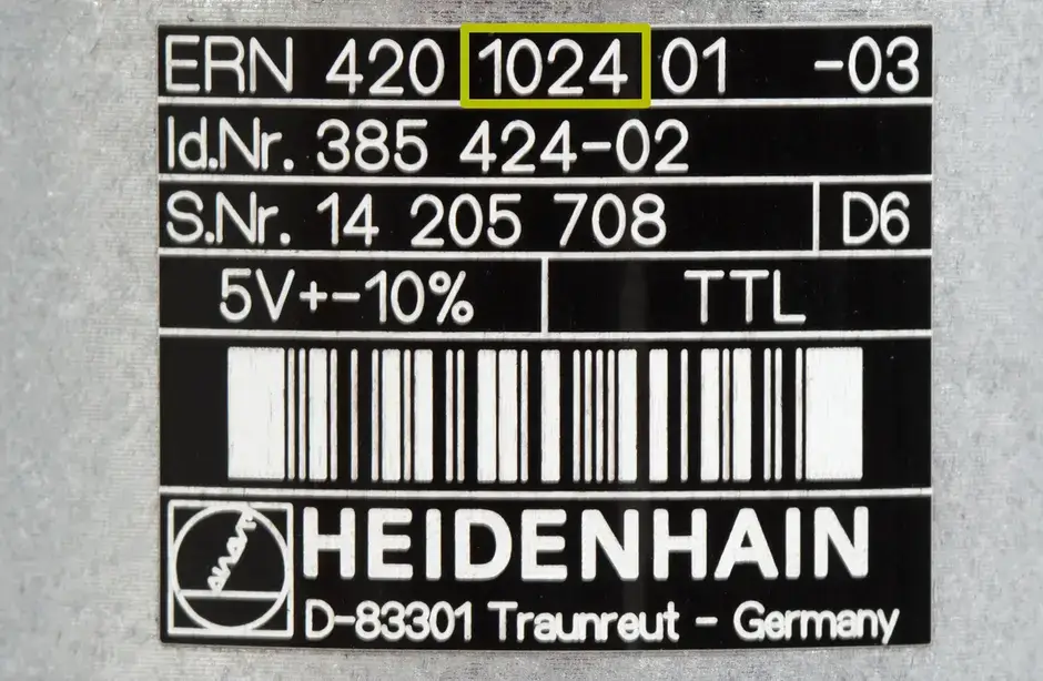
Line count on the ID label
The first number after the model designation is the “line count”.
Take, for example, the ERN 420 1024:
- Model designation: ERN 420
- Line count: 1024
The EnDat02 and EnDat22 order designations define different technical parameters that are important for the connection of an encoder. This includes the availability of incremental signals, the typical voltage supply range, the command set, and the maximum clock frequency. Among other things, the following table applies:
| Incremental signal | Voltage supply range | Command set | Max. clock frequency | |
| EnDat02 | With 1 VPP incremental signal | 3.6 V to 5.25 V or 3.6 V to 14 V | Command set 2.2 | ≤ 2 MHz or ≤ 8 MHz or 16 MHz |
| EnDat22 | Without incremental signal | 3.6 V to 5.25 V or 3.6 V to 14 V | Command set 2.2 | ≤ 8 MHz or 16 MHz |
Please refer to the interface brochure with its additional information and exceptions noted in the technical data.
For more information about EnDat, please refer to https://endat.heidenhain.com/.
Resolution is the smallest-possible measuring step. This means that, the higher the resolution, the more precisely a value can be displayed.
Measuring accuracy is the maximum value by which the encoder may deviate from the correct value.
AMO products
Please contact the Encoder & DRO Support group to setup a service return authorization (SRA): techsupportHC@heidenhain.com
After receiving the SRA, please ship the unit to our US headquarters in Schaumburg, IL:
HEIDENHAIN CORPORATION
333 East State Parkway
Schaumburg, IL 60173
Contact the Encoder & DRO Support group:
techsupportHC@heidenhain.com
Mounting instructions:
For more information, visit:
https://www.amo-gmbh.com/en/downloads/mounting-instructions/
CAD data:
For more information, visit:
https://www.amo-gmbh.com/en/downloads/cad-files/
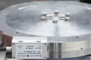
Encoder alignment
Please check the alignment of the scanning head relative to the scale tape.
The points must be on the same side (see image).
Please return both scanning heads and the MHS box.
The heads are calibrated with the MHS box.
The scale tapes can remain in the machine.
- STU-60: for the POSI 6 series with 1VPP or TTL
- STU-20: for the POSI 5 series with 1VPP or TTL
- ATU-2: BISS C and SSI interface
- PWM2x: EnDat, DRIVE-CLiQ, partly 1VPP and TTL
- PWT101: EnDat (1VPP and TTL with AMO adapter)
Please send your request, including the relevant ID and serial number, to techsupportHC@heidenhain.com.
Signal converters
Please check whether the TFTP client has been activated:
- Press the Windows key + “R”.
- Enter “appwiz.cpl” and press enter.
- The “Programs and features” function appears.
- Click “Activate or deactivate Windows features” on the left side.
- A window with the available Windows features appears. Select the check mark for “TFTP client” if it has not already been selected.
- The TFTP Windows client is installed and is immediately available without restarting the system.
A firewall might be blocking the connection setup. Try temporarily deactivating the firewall.
The firmware of the EIB 7xx can be updated as follows:
- Download the current firmware.
- Save the update file to “C:\temp\EIB\update_633281-xx.flash”.
- Press the Windows key + “R”.
- Enter “cmd” and press enter.
- Enter “tftp –i 192.168.1.2 put C:\temp\EIB\update_633281-xx.flash tmp\update.flash” and press enter (adjust IP address as needed).
- When the file has been successfully transferred, the status LED of the EIB 7xx goes out. The voltage supply must not be switched off at this time, and no TCP commands may be sent to the EIB 7xx.
- When the status LED is active again, the EIB 7xx can be restarted.
For more information about performing a firmware update, refer to the Firmware Update section of the User’s Manual. The current User’s Manual can be found in the “User documentation” section of the download area. Unter “Filebase: documentation”, Select the following fields in the dropdown menu:
- Category: Evaluation units
- Product family & software solutions: EIB
With the network setting tool on the driver CD (driver CD > EIB_7xx > windows > tools > networksettings > networksetting.exe), you can check the firmware version of the connected EIB 7xx.
You can find it under Evaluation Units in the download area. Select the following fields in the dropdown menu:
- Category: Evaluation units
- Product family & software solutions: EIB
If the EIB 7xx cannot be reached, then the default network settings of the EIB 7xx can be loaded by means of a reset. To do this, press and hold the reset button on the back of the device for more than ten seconds.
For more information, please refer to the section “Reset modes supported by the product” in the Operating Instructions. To do so, select the following fields in the dropdown menu under Filebase: documentation.
- Category: Evaluation electronics
- Product family & software solutions: EIB
Inspection and testing devices
Check whether the hardware is connected and switched on. Another cause may be that the hardware driver for the ATS software is not installed. Please manually install the driver.
You do not need a product key for the standard functions described in the User’s Manual.

