Objectives
- Become familiar with:
- Mechanical components of a machine tool
- Electronic components of a machine tool
- Types of controls and principle of control
- Commit to memory:
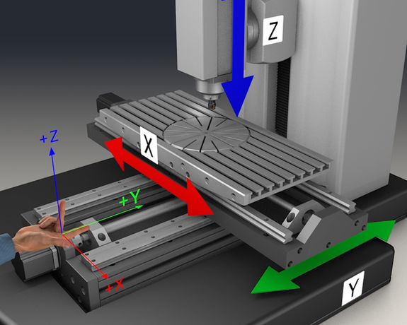
- Axis designations and axis directions
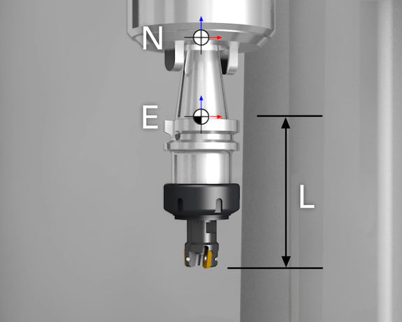
- Presets


Moving the axes:
Activating presets:
Getting to know the tool types and cycles:
Calculating the cutting data:
Multiple-choice questions:
For each question, only one of the answers is correct.

This button removes one of the wrong answers.
Only use the solution button for questions that, if you cannot answer them, would prevent you from continuing by yourself.
The use of the solution button is evaluated as an error.
Each error increases the error counter by one.![]()
Do you want to cancel the simulation?
As its name suggests, the NC interpreter interprets the NC program, analyzing its syntax and converting the information into an internal format. For each positioning block, it forwards the position of the contour corners, the required type of movement (linear or circular), and the associated feed rate to the geometry data processor. The interpreter forwards other switching functions, tool calls, etc. directly to the PLC. The control synchronizes the resulting commands with the geometry data. For example, a tool change will only take place after the control has completed the previous geometry block.
The velocity feedforward control makes adjustments to speed and acceleration, taking the geometry and dynamics of the axis drives into account.
Geometric transformations include datum shifts, rotations, and mirroring. The geometry data processor calculates the positions to be approached, taking these transformations into account.
In addition, the geometry data processor accounts for any compensations, such as tool length compensation or tool radius compensation. If you programmed a tool radius compensation (RL or RR), the current tool data is used to calculate offsets to the programmed contour.
The interpolator calculates so-called intermediate points for a contour section specified in the NC program. Thus, the contour movement, resulting from the simultaneous movement of multiple axes, is subdivided into sections for each individual axis. This means that each axis can change its position independently of the other axes.
The interpolator accounts for the velocity profile defined by the velocity feedforward control and the kinematic transformation of the coordinates in case non-Cartesian machine kinematics are used.
These nominal values are adopted as command variables in the corresponding control loops.
