Machine tool
Machine design
The classification criteria below are not exhaustive. They are only supposed to provide an overview.
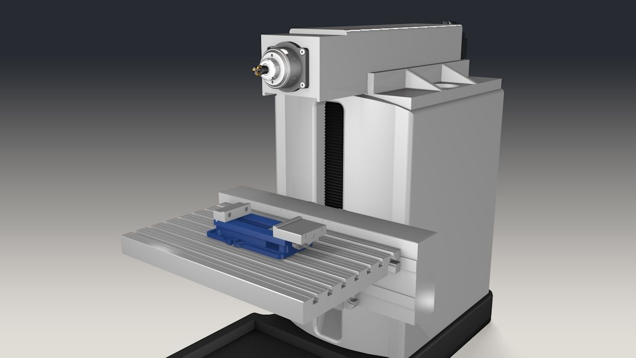
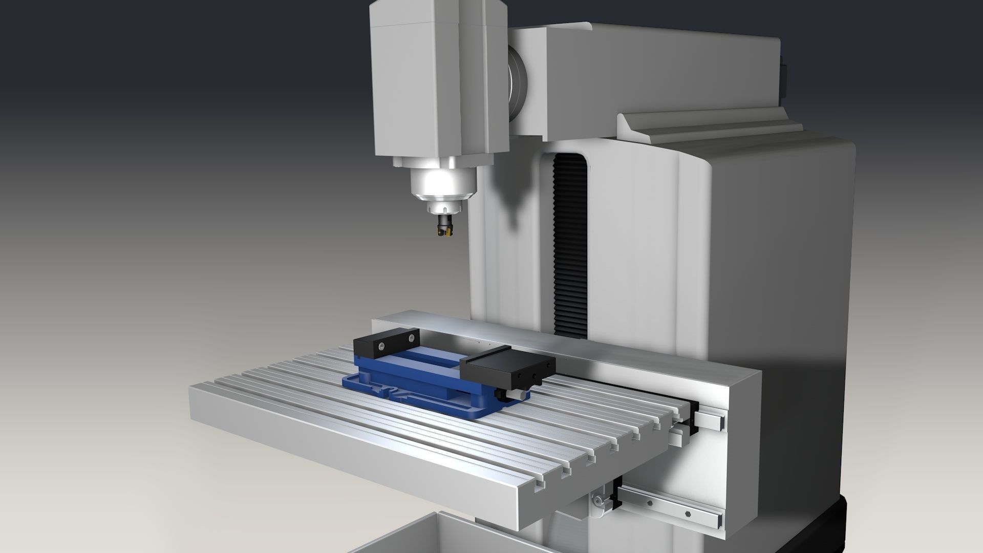
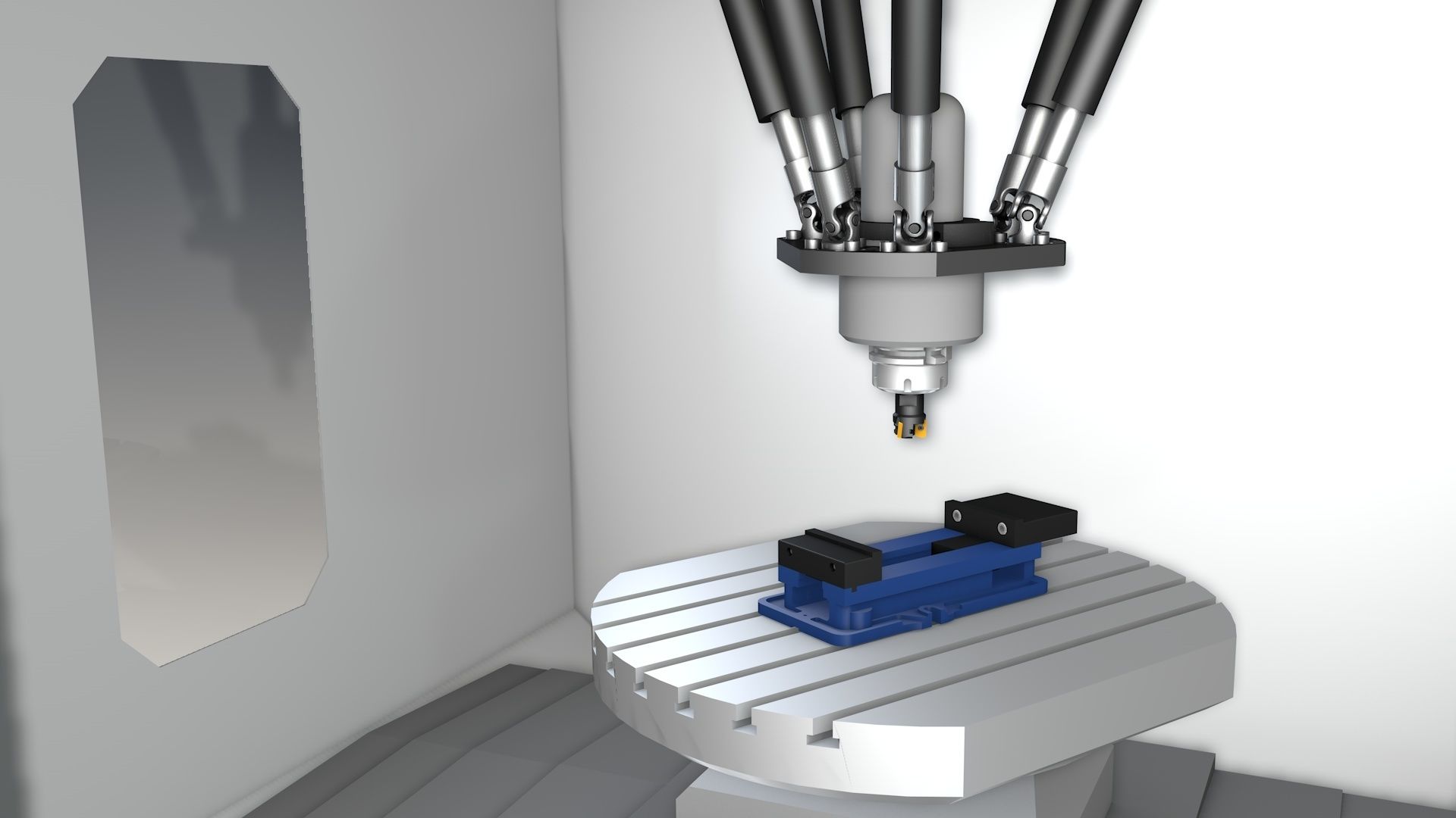
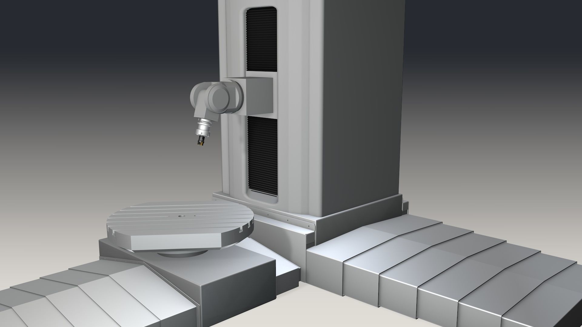
- Rough classification based on the machine design:
- Horizontal milling machine with horizontal tool spindle
- Vertical milling machine with vertical tool spindle
- Parallel kinematic machine tool
1 | 2 | 3 |
|
|
|
Machine design
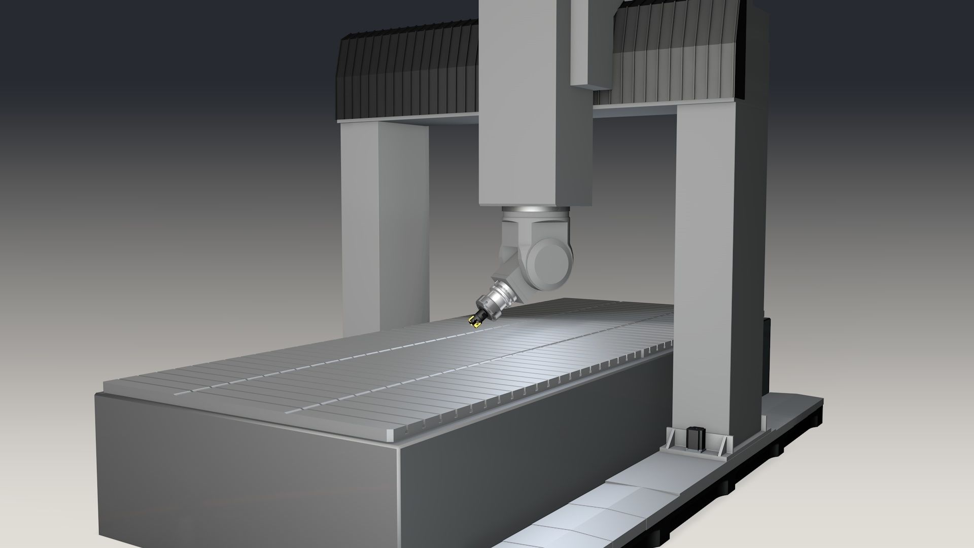
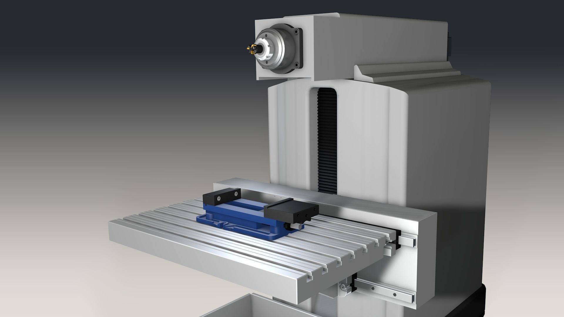
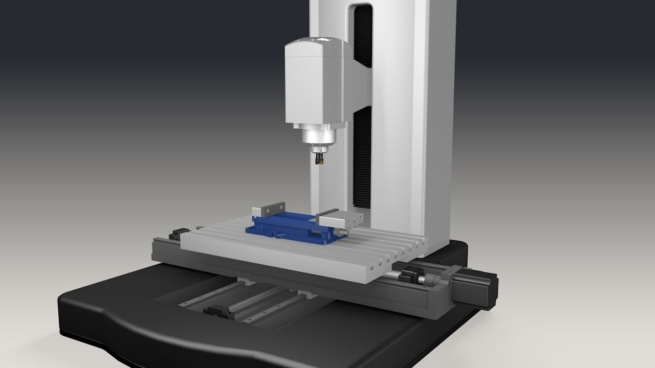
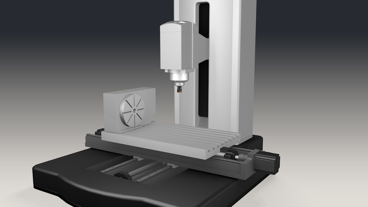
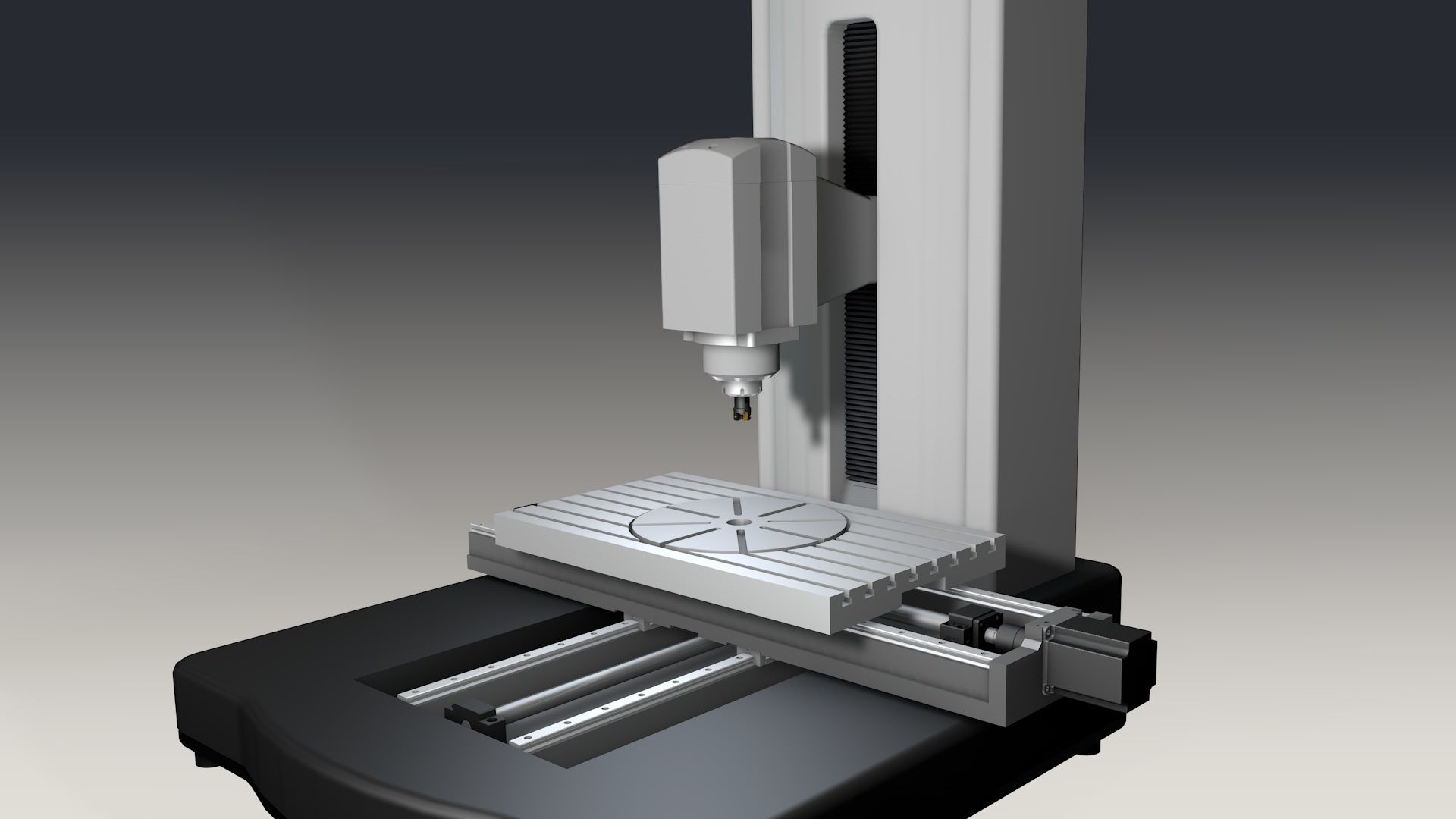
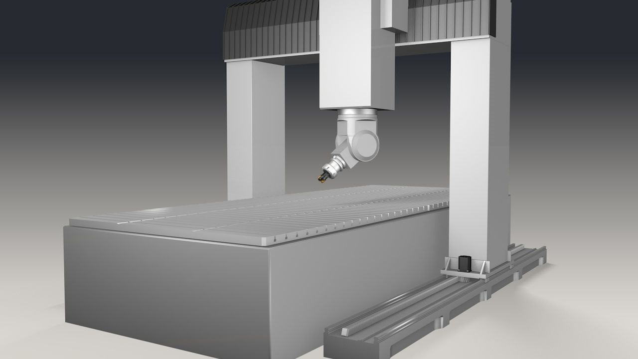
- Further classification based on the machine design:
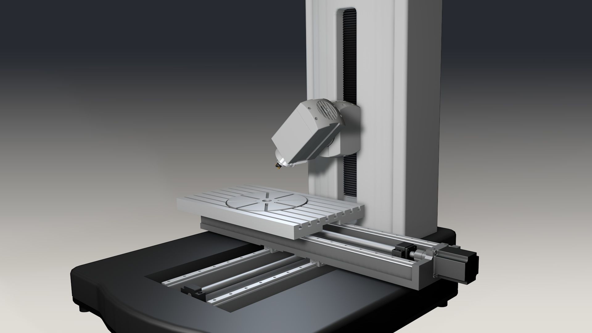
- Design with traversing column
- Portal or gantry design
- Knee-type design with frame or knee-type design with bed
- XY table design and XY bed design
1 | 2 | 3 | 4 |
|
|
|
|
Number of axes
- Classification based on the number of axes:
- Three linear axes
- Three linear axes and one rotary axis
- Three linear axes and two rotary axes
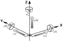
Each milling machine has at least three linear axes (X, Y, and Z). Based on these three axes, it is possible to define any position in the so-called Cartesian coordinate system.
Coordinate systems
In addition, some machines are equipped with so-called parallel axes (U, V or W), such as the spindle sleeve of a boring mill.
1 | 2 | 3 |
|
|
|
|
Kinematics
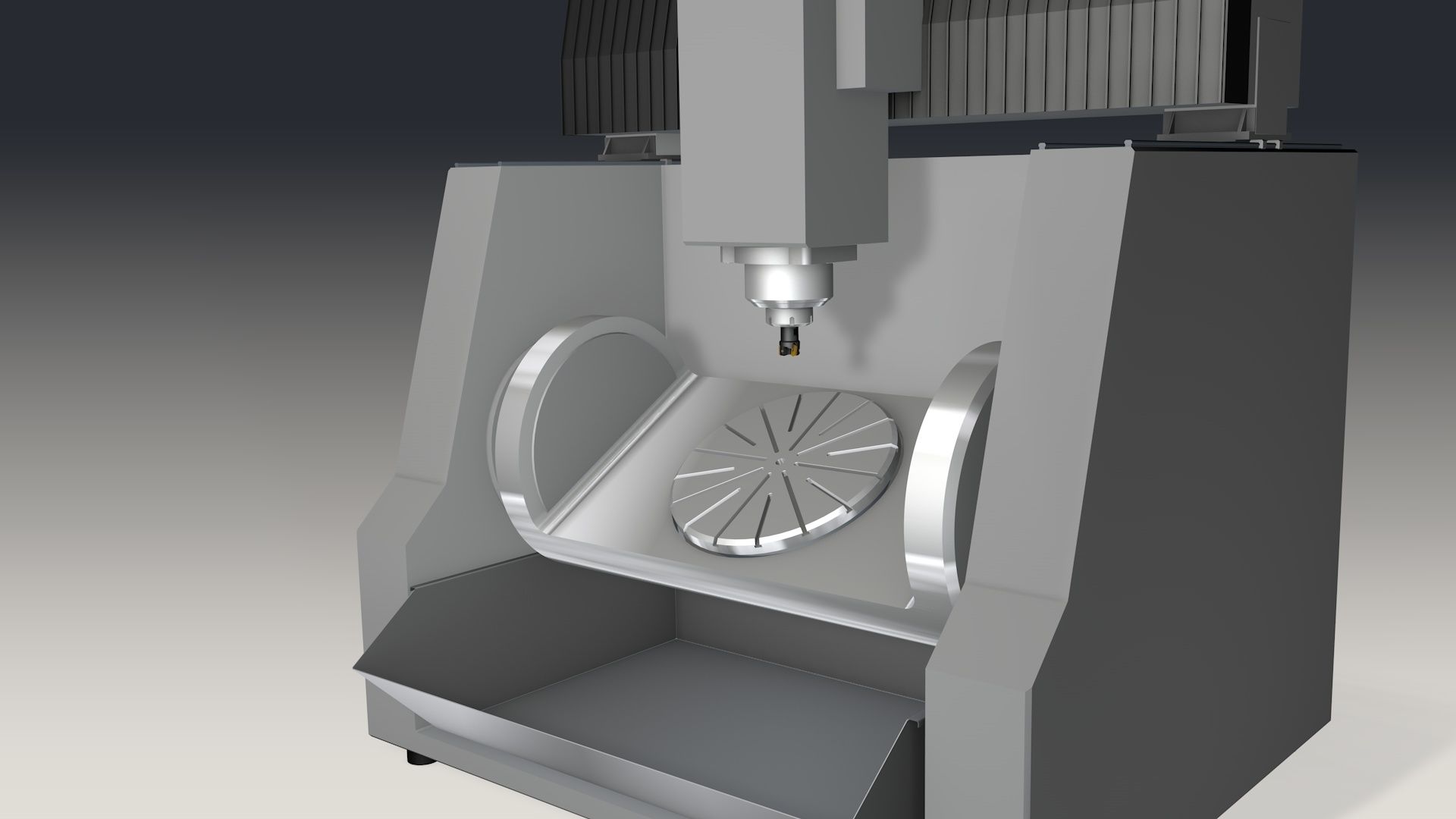
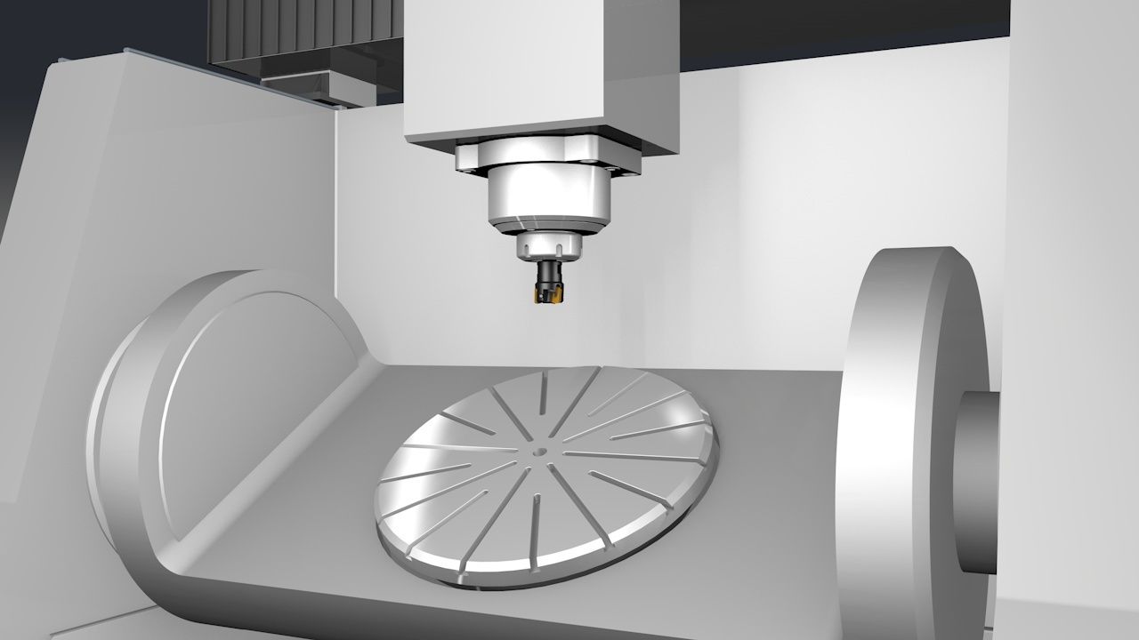
- Classification of 5-axis milling machines based on their kinematics:
- Table-table kinematics, both rotary axes are located in the table
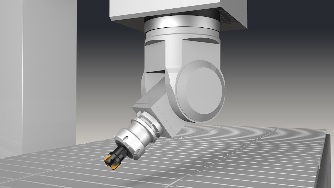
- Head-table kinematics, one rotary axis is located in the head, one in the table
- Head-head kinematics, both rotary axes are located in the head
1 | 2 | 3 |
|
|
|
Feed drives
The machine axes move either the tool or the workpiece.
- Essential purposes of the feed drive:
- Realize the required contouring speed and acceleration
- Reach the predefined positioning and contouring accuracy
The quality of the system components in use directly impacts how these purposes will be fulfilled.
- Frequently used drive types:
- Rack and pinion
- Recirculating ball screw
- Linear drives
- Hydraulic drives
Rack and pinion
For rack-and-pinion drives, the rotary axis is perpendicular to the displacement direction of the rack.
- Possible motions:
- Create a rotary motion by displacing the rack using a hydraulic cylinder
- Create a linear motion using an electric motor
Rack-and-pinion or rack-and-worm solutions are mainly used for machines with large traverse distances.
Recirculating ball screw
A recirculating ball screw converts a rotary motion of the motor into a linear motion of the machine axis.
- Operating principle:
- Two nuts include cages that contain balls.
- The recirculating ball screw is set in rotation.
- The balls inside the cage perform an endless motion around the ball screw.
- This rotation causes a linear motion of the nuts.
- The nuts cause a linear motion of the flange-mounted machine components.
- Advantages:
- Very high mechanical efficiency due to the low rolling friction
- No slip stick
- Low wear and tear and thus a long lifetime
- Low temperature rise
- Excellent position accuracy and repeatability, at the same time no mechanical play and sufficient rigidity
- High traversing speed
- Advantages over gear racks:
- Higher efficiency due to rolling friction as compared to sliding friction
- No mechanical play through mutual tensioning of the nuts
Linear drives
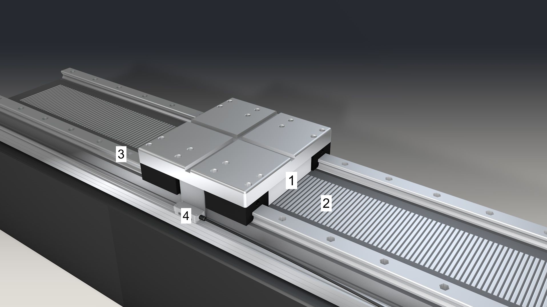
- A linear axis with a linear drive is constructed as follows:
- Primary part with three-phase winding
- Secondary part with permanent magnetic element or rotor bars
- Linear guides
- Linear encoder for direct path measurement
- Advantages:
- No mechanical transmission elements thanks to the direct linear motion
- No wear and tear and thus a long lifetime
- No reversal error, no elastic behavior of the power train, high static and dynamic rigidity
- Low total mass and reduced number of components
- Low following error, good position accuracy, even at high traversing speeds
- High acceleration capacity
- Disadvantages:
- Low efficiency, high power loss
- Due to the large heat buildup, a liquid cooling system is required
Hydraulic drives
If the position accuracy requirements for the machine axes are low, hydraulic drives can be used as well.
Linear movements are usually produced by means of piston-cylinder drives. Hydraulic motors produce a rotary motion.
- Examples:
- Tailstock
- Steady rest
- Advantages:
- Quick response within wide torque or speed ranges
- Continuously variable speed
- High torque
- Constant torque output
- Compact size
Indirect path measurement
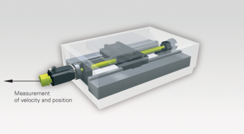
For indirect path measurement, a rotary encoder is flange-mounted to the recirculating ball screw of the axis drive. The rotary encoder ascertains the angular position of the motor or recirculating ball screw. Based on this value, the system calculates the position of the axis slide, taking the gear ratio of the gearbox and the pitch of the ball screw into account.
- Operating principle:
- The rotary encoder contains a circular carrier (disk) made of glass with a scale that is scanned optically.
- A scanning head optically scans the graduation and generates an electric signal.
- Subsequent electronics subdivide the signal into counting pulses.
- The distance traversed by the axis slide is thus determined indirectly from the rotational movement and screw pitch.
Direct path measurement
With direct distance measurement, the measuring head of a linear encoder ascertains the current position of the machine axis directly on the linear scale. The measuring head moves together with the axis slide, the housing of the linear encoder with the scale is stationary.
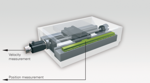
- Operating principle:
- The linear encoder contains a measuring standard in the form of a carrier made of glass or steel that includes a graduation.
- The scanning head moves along the graduation without contact, optically scans the graduation and generates an electric signal.
- Subsequent electronics generate counting pulses from this signal.
- Depending on the traverse direction, the control will add or subtract the counting pulses.
The mode of operation of rotary and linear encoders is the same.
However, the linear encoder measures the position of the axis slide directly at the scale.
A comparison shows the advantages of the linear encoder.
Incremental encoders
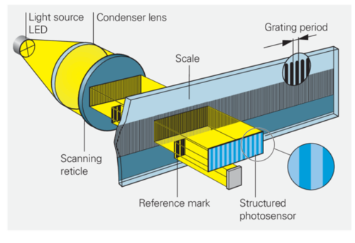
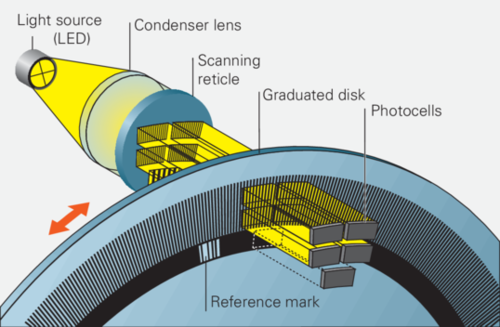
With the incremental measuring method, the graduation consists of a periodic line structure. The position information is obtained by counting the individual increments (measuring steps) from some datum.
Since an absolute reference is required to ascertain positions, the scales or scale tapes are provided with an additional track that bears a reference mark. The absolute position on the scale, established by the reference mark, is gated with exactly one signal period. Before the control is able to make an absolute reference or find the last selected preset again, the reference mark must be traversed.
Absolute encoders
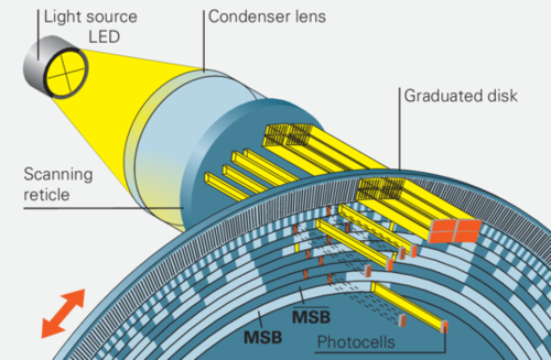
With the absolute measuring method, the position value is available immediately after the encoder has been switched on. Referencing is not required, i.e. there is no need to move the axes to find the reference position. The absolute position is obtained from the graduation, which is based on the binary number system.
Photoelectric scanning principle
The light passing through the line pattern falls onto photo elements located behind a scanning grid.
Due to the relative motion of the scale and scanning unit, the ticks and gaps of the scale alternately coincide with those of the scanning grid.
The photo elements convert the periodically changing luminous flux into electrical sinusoidal signals. Subsequent electronics connected downstream generate direction-dependent counting pulses from these signals.
Besides these optical methods, there are other scanning principles, such as magnetic scanning.
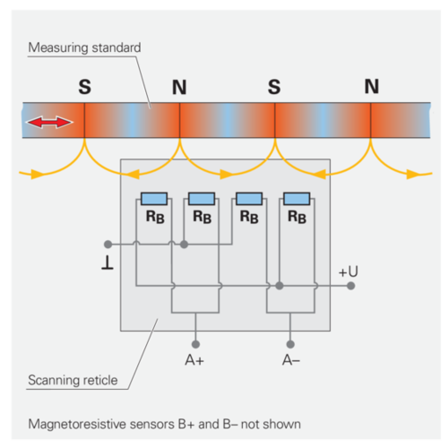
Types of control
CNC is short for Computerized Numerical Control.
- Types of control:
- Point control
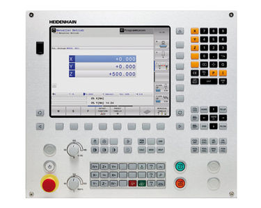
- Straight-cut control, such as the TNC 128
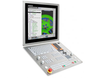
- Contouring control, such as the TNC 640
TNC is short for Tip Numerical Control.
Tip indicates that you can write NC programs directly at the control system. Before controls were equipped with an internal memory, programmers used punched tape for storing the data.
2 | 3 |
|
|
Point control
Point controls allow to move the axes from point to point. Rapid traverse is used to position the tool at the programmed points.
- Further features:
- while being positioned in rapid traverse, the tool is not in contact with the workpiece
- depending on the control, the axis drives are operated simultaneously or separately
- the control will neither coordinate nor interpolate the axes
- Typical applications:
- Drilling
- Spot welding
Straight-cut control
In addition to the features available for a point control, a straight cut control enables single-axis milling of straight lines at a defined machining speed.
- Further features:
- while the tool is being positioned in single-axis traverse, it is in contact with the workpiece
- the tool path is feed-controlled
- the axis drives are operated alternately
- the control will perform a simple coordination of the axes
- Typical applications:
- Face milling
- Mill simple contours (straight surfaces)
A straight-cut control allows to machine cylindric or concentric workpieces at a turning machine.
Contouring control
A contouring control allows to move two (2-D) or three (3-D) axes simultaneously. The interpolator coordinates the speeds of the axes. In addition to single-axis straight surfaces, you can machine inclined contours in a plane or in 3-D space as well as circular contours.
- Classification based on the number of interpolating axes:
- 2-D contouring control, e.g. two defined axes for the contour paths and one defined axis for tool infeed
- 2.5-D contouring control, e.g. any two defined axes for the contour paths and the remaining axis for tool infeed
- 3-D contouring control, e.g. contour movements in 3-D space with at least three axes simultaneously (in addition to the linear axes, up to three rotary axes are possible)
- Typical applications:
- Full-surface machining with dual-spindles
- Freeform surfaces
With the current control models, it is possible to perform turning operations at milling machines and milling operations at lathes.
Components of a control system
- Overview:
- Visual display unit with operating panel
- Power supply module
- Main computer (MC)
- Controller units (CC, also called controller computers)
- Spindle drive
- Feed drives
- Bus system
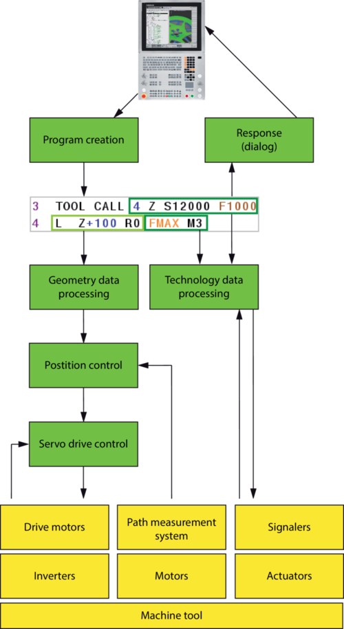
Function blocks of a control system
Functions
- Overview:
- Provision of energy (power supply, power conversion)
- Control features (creation of geometry, feedback control, and sensors)
- Safety and protection features for staff and facility
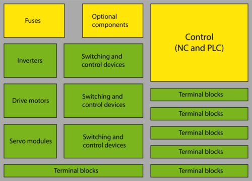
Among others, the electrical cabinet houses the controller units (CCs).
Feedback control
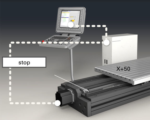
Feedback control means to measure an actual value (controlled variable) within the controlled system and continually compares it to the desired nominal value (command variable).
In case of deviations, the controller uses a manipulated variable to minimize the deviation.
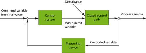
For example, a control loop monitors the axis motion so that a programmed position can be approached precisely and with the correct speed.
Precise control of an axis is a complex procedure, which will be explained extremely simplified here.
- Operating principle:
- The NC control calculates the distance to be traversed in each axis, and transmits this information as the nominal position value to the controllable drive.
- A position encoder continually provides feedback on the change of the slide position to the NC control.
- The feedback control system of the control continually compares the reported actual position to the specified nominal value.
- As long as the nominal position has not yet been reached, the drive remains in motion.
- When the nominal position has been reached, the control stops the axis at this position.
