Coordinate systems

Machine coordinate system
For the control to traverse an axis according to a defined path it requires a reference system.
A paraxially mounted linear encoder on a machine tool serves as a simple reference system for linear axes. The linear encoder represents a number ray, a unidimensional coordinate system.
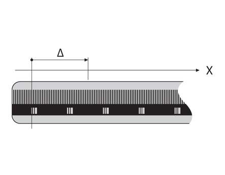
To approach a point on the plane, the control requires two axes and therefore a reference system with two dimensions.
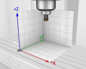
To approach a point in the space, the control requires three axes and therefore a reference system with three dimensions. If these three axes are configured perpendicular to each other this creates a so-called three-dimensional Cartesian coordinate system.
Cartesian coordinate system
- Characteristics:
- The three directions in the Cartesian coordinate system are specified as the axes X, Y, and Z.
- The axes are mutually perpendicular and intersect at one point: the datum (origin).
- An absolute coordinate designates the distance to the datum along a single axis.
Right-hand rule
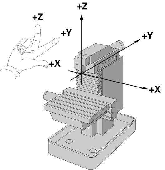
On a machine tool, each linear axis is assigned to a direction in the Cartesian coordinate system.
- Definition:
- The thumb of the right hand points in the X+ direction
- The index points in the Y+ direction
- The middle finger is splayed out perpendicularly to the thumb and index and points in the Z+ direction
Tip
When programming, always assume that the tool is in motion!
Thus, the right-hand rule is always valid, no matter if the machine axis is in the table or in the head.
Axis layout
The axes U, V and W are secondary axes parallel to the linear axes X, Y and Z. Rotary axes are designated as A, B and C.
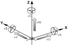
Linear axis | Parallel axis | Rotary axis |
|---|---|---|
X | U | A |
Y | V | B |
Z | W | C |
Polar coordinates
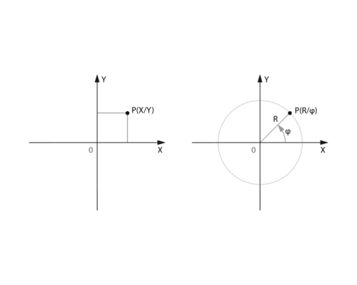
In a Cartesian coordinate system, a point P in a plane is defined by its X and Y values. → P(X, Y)
In a polar coordinate system, a point P is defined by its distance to the pole and by its angle φ relative to the positive X axis.
The distance between point P and the pole is designated as the radius R.→ P(R, φ)
Besides programmed axis movements, the control allows you to manually position the axes.
Tip
When moving any axis, always assume that the tool is in motion.
This means that an axis movement in the +Z direction will increase the distance between the tool and the workpiece if the tool is positioned above the workpiece before it starts to move. For this, it does not matter whether the movement is performed by the table or the head.
Now, practice moving the axes.
Elapsed time for exercise
Symbol overview
Symbol | Meaning |
|---|---|
| Reference point R |
| Machine datum M |
| Workpiece datum W |
Symbol | Meaning |
|---|---|
| Tool carrier reference point T |
| Tool change position B |
| Tool shank point N |
| Tool set point E |
Reference point

The reference point R identifies a specified position in an axis system. You only need the reference point if you use an incremental path measurement system.
When a machine axis moves, the corresponding position encoder generates an electrical signal. The control evaluates this signal and calculates the distance covered.
In order to determine the accurate actual position of the machine axis, this distance must reference a defined starting point, i.e. reference point R.
In case of a power failure, the association between the axis position and the calculated actual position is lost.
Tip
The machine manufacturer defines reference point R. This point cannot be changed.
If you use absolute encoders, there is no need to reference the axes. Once the control has been switched on, it knows the exact positions of all components.
Machine datum
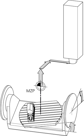
(= machine datum)
The machine datum M is a defined position in the machine coordinate system.
Since the position of the machine datum M is independent of the axis positions and the workpiece position, the machine datum M is used as a reference point for constant positions. These constant positions include e.g. the tool change position B.
Tip
The machine manufacturer defines the machine datum M. This point cannot be changed.
The machine datum M can also lie outside the traverse range.
NC blocks referencing the machine datum M must include the miscellaneous function M91 in addition to the coordinate data.
Workpiece datum
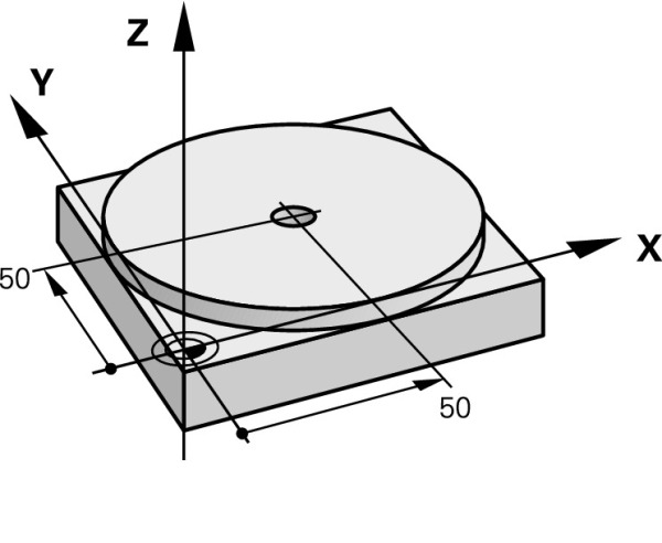
The workpiece datum W serves as the reference point for coordinate input in the NC program.
When you take over coordinates from the technical drawing, the workpiece datum W you determine is located at the dimensioning origin set in the drawing.
Tip
You will not enter the position of the workpiece datum W manually at the control, but after the workpiece blank has been clamped. To do so, use a cutting tool to scratch the workpiece blank or probe it using a 3-D touch probe.
Workpiece datum—scratching
Tip
Clamp the workpiece blank parallel to the machine axes and align it before scratching it with a cutting tool.
Scratching must be done separately for each axis. The scratched position can be used as the actual position. The control will account for the cutter radius automatically.
Workpiece datum—probing
Tip
There is no need to align the workpiece blank before probing because the basic rotation will be determined automatically by the 3-D probing system and be accounted for by the control.
- Please note the correct order of steps:
- Measure the basic rotation
- Once the basic rotation is active, set the workpiece datum
A 3-D touch probe allows you to set up workpieces with greater speed and accuracy. The control provides various touch probe cycles for automatic workpiece inspection and tool compensation.
The control offers the Preset management as a place for central management of all required presets. You can determine and save these presets in advance, while setting up, or during program run.
You can activate a stored preset either manually or using Cycle 247 in your NC program.
Now, practice activating presets.
Elapsed time for exercise


