First steps

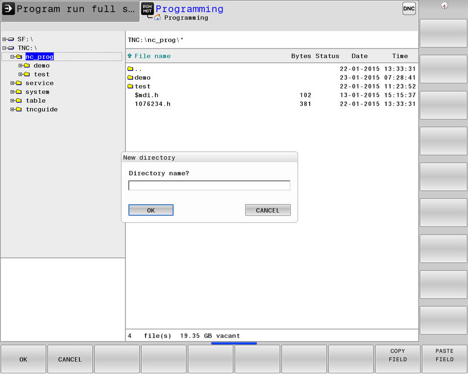
Creating a directory
 |
| |
 |
|
 |
| |
 |
|
 |
| |
| ||
 |
| |
 |
|
Tip
Use only letters, numbers, and underscores for directory and file names.
The path, including all drive characters as well as the directory, file name and extension, must not exceed 255 characters.
Creating an NC program
 |
| |
 |
|
If you wish to save the NC program in a directory other than the currently active directory:
 |
| |
 |
| |
 |
|
| ||
 |
| |
 |
| |
 |
|
Tip
File names should not exceed 25 characters; otherwise the control cannot display the entire name.
Copying, renaming, or deleting a file
| ||
 |
| |
| ||
 |
| |
 |
| |
 |
| |
Tip
When you start the copying process with the ENT key or the OK soft key, the TNC displays a pop-up window with a progress indicator.
| ||
 |
| |
Notice
Caution: Possible data loss!
The DELETE function permanently deletes the file. The file is not automatically backed up by the control, e.g. to a recycle bin, before being deleted. Files are irreversibly deleted by this function.
- Make regular back-ups of important data to external drives
| ||
 |
| |
Procedure
Immediately after creating a new NC program, you define an unmachined workpiece blank.
To define the workpiece blank at a later time, proceed as follows: | ||
 |
| |
 |
| |
 |
| |
 |
| |
Tip
You only need to define the workpiece blank if you wish to run a graphic test on the NC program or work with FK programming!
The control can depict various types of blank forms:
Soft key | Function |
|---|---|
| Rectangular blank |
| Cylindrical blank |
| Rotationally symmetric blank of any shape |
Tip
If you select a workpiece blank of cylindrical or any rotationally symmetric form, define whether the control is to interpret the programmed diameter values as radius or diameter.
Example
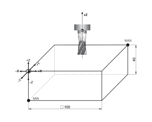
The sides of the cuboid lie parallel to the X, Y and Z axes. This blank is defined by two of its corner points:
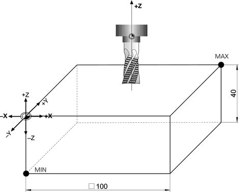
- MIN point: the smallest X, Y, and Z coordinates of the cuboid blank; enter as absolute values
- MAX point: the largest X, Y, and Z coordinates of the cuboid blank; enter as absolute or incremental values
Tip
Describe the blank with respect to the active preset.
The MIN point defines the blank on the left (X), front (Y) and bottom (Z).
The MAX point defines the blank on the right (X), at the rear (Y) and top (Z).
To define the BLK FORM workpiece blank, proceed as follows: | ||
 |
| |
 |
| |
 |
| |
 |
| |
| ||
 |
|
BLK FORM 0.1 Z X+0 Y+0 Z-40 | Spindle axis and minimum point |
BLK FORM 0.2 X+100 Y+100 Z+0 | Maximum point |
Elapsed time for exercise
Excellent!
Continue immediately with the next learning topic or the next exercise.
You can do better!
Repeat the exercise, just to be on the safe side.
Did you have difficulties?
Maybe repeat the topic in the learning module.
Obviously, some items remained unclear!
We recommend that you repeat the learning module.
Unfortunately, you exceeded the maximum number of wrong answers.
Repeat the learning module and then try the exercise again.

Elapsed time for exercise
Excellent!
Continue immediately with the next learning topic or the next exercise.
Well done!
Would you like to repeat the exercise to obtain an excellent result?
You can do better!
Repeat the exercise, just to be on the safe side.
Did you have difficulties?
Maybe repeat the topic in the learning module.
Obviously, some items remained unclear!
We recommend that you repeat the learning module.
Unfortunately, you exceeded the maximum number of wrong answers.
Repeat the learning module and then try the exercise again.
General information
To use a tool you must call it at the desired position in the NC program.
Key | Meaning | Function |
|---|---|---|
 | Tool Call Call the tool |
|
Machine
Refer to your machine manual.
The tool change function can vary depending on the individual machine tool.
Input parameters
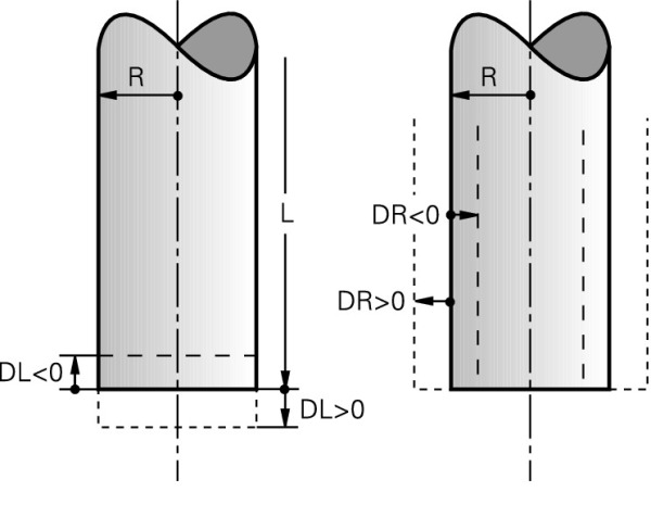
- Tool number or tool name
- Spindle axis X, Y, Z
- Spindle speed S or cutting speed VC
- Feed rate F
- Delta value for tool length DL
- Delta value for tool radius DR
- Delta value for rounding radius of the tool DR2
Tip
You can enter a delta value of up to ± 99.999 mm.
Positive delta values mean oversize, negative mean undersize.
Procedure
To call a tool, proceed as follows: | ||
 |
| |
 |
| |
| ||
 |
| |
 |
| |
| ||
 |
| |
| ||
 |
| |
TOOL CALL 5 Z S8500 | Tool call with tool number and spindle speed |
TOOL CALL "DRILL_118_D10" Z S( VC = 180 ) F800 DL+1 DR+0.5 | Tool call with tool name, cutting speed, feed rate and delta values |
Linear motion, absolute Cartesian coordinates
Absolute input values always reference the workpiece datum.
For the input of target coordinates, enter Cartesian coordinate values for the X, Y, and Z axes.
Tip
The Contour Programming learning module contains detailed information on this and other path functions, as well as descriptions of the additional functions APPR, DEP, and FK.
Procedure
To program a linear block, proceed as follows: | ||
 |
| |
 |
| |
 |
| |
 |
| |
 |
| |
| ||
 |
| |
| ||
 |
| |
 |
| |
Tip
Programmed coordinates and programmed feed rates are modally effective.
FMAX is effective only in the current block.
Possible feed rate input
Soft key | Function |
|---|---|
 | Rapid traverse
|
 | Feed rate from the TOOL CALL block |
 | Programmed feed rate
|
 | Feed per revolution
|
 | Tooth feed rate
|
Elapsed time for exercise
Excellent!
Continue immediately with the next learning topic or the next exercise.
Well done!
Would you like to repeat the exercise to obtain an excellent result?
You can do better!
Repeat the exercise, just to be on the safe side.
Did you have difficulties?
Maybe repeat the topic in the learning module.
Obviously, some items remained unclear!
We recommend that you repeat the learning module.
Unfortunately, you exceeded the maximum number of wrong answers.
Repeat the learning module and then try the exercise again.
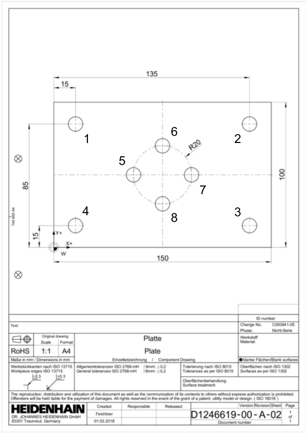
Tip
The following exercise will not result in a coherent or executable NC program.
The only purpose of this task is to practice entering coordinates in a plane.

The required L key and the associated linear movement are explained in detail in another topic.
Elapsed time for exercise
Excellent!
Continue immediately with the next learning topic or the next exercise.
Well done!
Would you like to repeat the exercise to obtain an excellent result?
You can do better!
Repeat the exercise, just to be on the safe side.
Did you have difficulties?
Maybe repeat the topic in the learning module.
Obviously, some items remained unclear!
We recommend that you repeat the learning module.
Unfortunately, you exceeded the maximum number of wrong answers.
Repeat the learning module and then try the exercise again.
Tip
The following exercise will not result in a coherent or executable NC program.
The only purpose of this task is to practice entering coordinates in a plane.

The required L key and the associated linear movement are explained in detail in another topic.
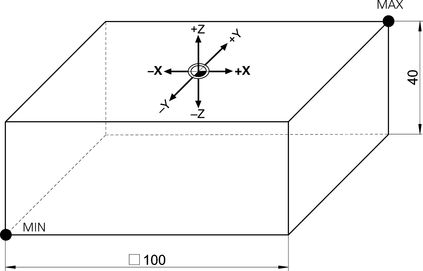
- Pay particular attention to the position of the workpiece datum because it is different in every graphic!
Selecting an NC block
Proceed as follows to place the cursor directly on the NC block you want to edit: | ||
 |
| |
| ||
 |
| |
As an alternative, you can position it as follows:
  |
|
Editing an NC block
5 L X+20 Y-10 R0 F1000 M3 |
Proceed as follows to edit an NC block: | ||
 |
| |
| ||
 |
| |
| ||
 |
| |
| ||
 |
| |
| ||
 |
| |
 |
| |
Tip
By pressing the up or down arrow key, you can search the NC program for the word the cursor is on. For example, you can jump from one Tool Call block to the next.
You have the following options for concluding a modification:
 |
|
 |
|
5 L X-10 Y+25 RL F500 | Changes adopted |
5 L X+20 Y-10 R0 F1000 M3 | Changes discarded |
Deleting an NC block
To delete an NC block, proceed as follows: | ||
 |
| |
 |
| |
If you have unintentionally deleted an NC block, re-insert it into the NC program as follows: | ||
 |
| |
Tip
You can also use this function to cut and paste a block.
Elapsed time for exercise
Excellent!
Continue immediately with the next learning topic or the next exercise.
Well done!
Would you like to repeat the exercise to obtain an excellent result?
You can do better!
Repeat the exercise, just to be on the safe side.
Did you have difficulties?
Maybe repeat the topic in the learning module.
Obviously, some items remained unclear!
We recommend that you repeat the learning module.
Unfortunately, you exceeded the maximum number of wrong answers.
Repeat the learning module and then try the exercise again.

Milling | X | Y | Z |
|---|---|---|---|
Safe position | +150 | +150 | +100 |
Safety clearance | - | - | +5 |
Pre-position | -60 | +35 | +100 |
Ø | T | S | F1 | F2 | DZ | IZ | |
|---|---|---|---|---|---|---|---|
 | 10 | 5 | 8900 | 1100 | 2000 | -5 | 5 |
Ø) | Diameter |
T) | Tool number |
S) | Speed |
F1) | Machining feed |
F2) | Retraction feed rate |
DZ) | Max. machining depth |
IZ) | Infeed |
Procedure
To perform a test run, proceed as follows: | ||
 |
| |
 |
| |
 |
| |
 |
| |
 |
| |
 |
| |
You have the following options for the test run:
Soft key | Function |
|---|---|
 | Reset the workpiece blank and test the entire NC program |
 | Test each NC block individually |
 | Test the entire NC program |
 | Test the program up to a certain NC block |
 | Stop the test run This soft key only appears once you have started the test run. |
Viewing options
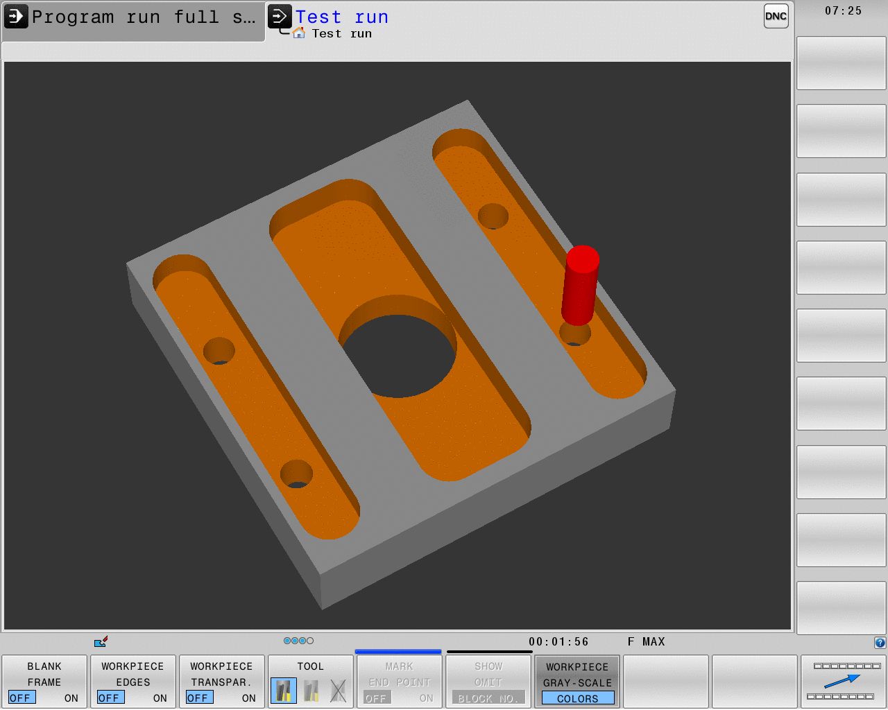
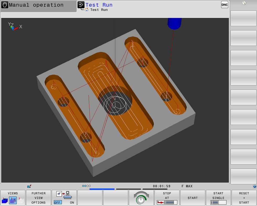
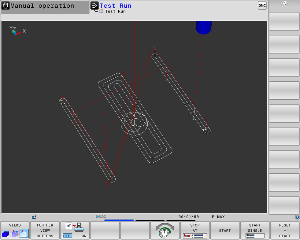
The Test Run operating mode features the following additional views:
Soft keys | Function |
|---|---|
| Volume view |
| Volume view and tool paths |
| Tool paths |
Tip
Besides the input of Cartesian coordinates presented earlier, the video also shows how to use polar coordinates.
The Contour Programming learning module contains detailed information on the input of various coordinates, other path functions, as well as descriptions of the additional functions APPR, DEP, and FK.


